A dive into the PE file format - PE file structure - Part 6: PE Base Relocations
A dive into the PE file format - PE file structure - Part 6: PE Base Relocations
Introduction
In this post we’re going to talk about PE base relocations. We’re going to discuss what relocations are, then we’ll take a look at the relocation table.
Relocations
When a program is compiled, the compiler assumes that the executable is going to be loaded at a certain base address, that address is saved in IMAGE_OPTIONAL_HEADER.ImageBase, some addresses get calculated then hardcoded within the executable based on the base address.
However for a variety of reasons, it’s not very likely that the executable is going to get its desired base address, it will get loaded in another base address and that will make all of the hardcoded addresses invalid.
A list of all hardcoded values that will need fixing if the image is loaded at a different base address is saved in a special table called the Relocation Table (a Data Directory within the .reloc section).
The process of relocating (done by the loader) is what fixes these values.
Let’s take an example, the following code defines an int variable and a pointer to that variable:
int test = 2;
int* testPtr = &test;
During compile-time, the compiler will assume a base address, let’s say it assumes a base address of 0x1000, it decides that test will be located at an offset of 0x100 and based on that it gives testPtr a value of 0x1100.
Later on, a user runs the program and the image gets loaded into memory.
It gets a base address of 0x2000, this means that the hardcoded value of testPtr will be invalid, the loader fixes that value by adding the difference between the assumed base address and the actual base address, in this case it’s a difference of 0x1000 (0x2000 - 0x1000), so the new value of testPtr will be 0x2100 (0x1100 + 0x1000) which is the correct new address of test.
Relocation Table
As described by Microsoft documentation, the base relocation table contains entries for all base relocations in the image.
It’s a Data Directory located within the .reloc section, it’s divided into blocks, each block represents the base relocations for a 4K page and each block must start on a 32-bit boundary.
Each block starts with an IMAGE_BASE_RELOCATION structure followed by any number of offset field entries.
The IMAGE_BASE_RELOCATION structure specifies the page RVA, and the size of the relocation block.
typedef struct _IMAGE_BASE_RELOCATION {
    DWORD   VirtualAddress;
    DWORD   SizeOfBlock;
} IMAGE_BASE_RELOCATION;
typedef IMAGE_BASE_RELOCATION UNALIGNED * PIMAGE_BASE_RELOCATION;
Each offset field entry is a WORD, first 4 bits of it define the relocation type (check Microsoft documentation for a list of relocation types), the last 12 bits store an offset from the RVA specified in the IMAGE_BASE_RELOCATION structure at the start of the relocation block.
Each relocation entry gets processed by adding the RVA of the page to the image base address, then by adding the offset specified in the relocation entry, an absolute address of the location that needs fixing can be obtained.
The PE file I’m looking at contains only one relocation block, its size is 0x28 bytes:
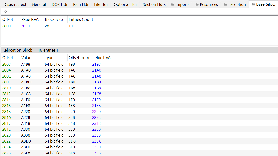
We know that each block starts with an 8-byte-long structure, meaning that the size of the entries is 0x20 bytes (32 bytes), each entry’s size is 2 bytes so the total number of entries should be 16.
Conclusion
That’s all.
Thanks for reading.